Underwater Acoustic Fish Tracking
Hello everyone! I’m Tejus, and I’m working with Prof. Spencer to develop a device for underwater acoustic power and data transmission. Eventually, we hope that this system will be useful for fish tracking applications. During the school year, my fellow researchers include and have included Martha Gao, Anneka Noe, Ilona Kariko, Aditya Khant, Christopher Ferrarin, Richard Zhang, and David Olumse.
Most fish tracking technology relies on the trilateration of an acoustic ping from an actively powered fish tag (Fig. 1). This is cumbersome, however, because the tag requires a battery that typically only lasts a few days and several hydrophones positioned at the surface of the ocean are required to capture and process the tag’s signal.
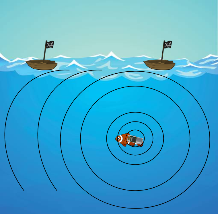
Figure 1: An active fish-tag transmits acoustic pings to several hydrophones on the surface.
For the past several years, researchers in ACE lab have been developing a system of battery-less fish trackers that would circumvent many of the current limitations in fish tracking devices. In order to achieve this, a “boat-side” array of nine piezoelectric transducers is used to transmit an ultrasound beam into the water. With precise control of the phase between transmitted bursts from each transducer, we can steer the beam of sound in a way that maximizes the constructive interference of waves at a certain location, which is important when considering the extensive loss that occurs as the signal spreads out underwater.
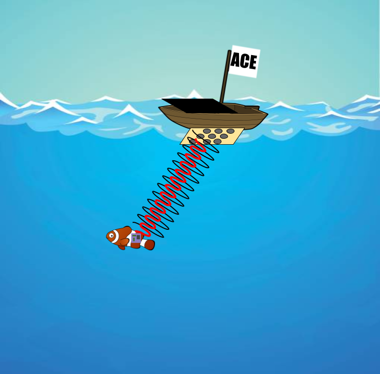
Figure 2: The ACE lab’s device uses the same array to transmit and receive power and data from a passive fish tag.
This phased array can also be used as a receiver for returning signals. When a transmitted acoustic burst bounces off an object (say, for example, a fish-tracking tag), that echo will return to the array and reach each transducer element at slightly different times. These delays can then be used to construct an image of where the object is, relative to the phased array.
Last summer, we were able to demonstrate this by locating a 0.2x0.3 meter metal plate placed at various locations in the HMC underwater robotics tank. However, we did this with a table full of equipment.

Figure 3: The equipment and electronics used to acquire the image (Fig. 4) from last summer occupied several tables.

Figure 4: One of the “images” acquired by our transmitting and receiving system last summer.
The dot represents the calculated location, and the crossbeams represent the area that the plate was located.
We have spent the past year redesigning our hardware to make it smaller and more usable. The improved device aims to consolidate both the transmitting and receiving signal processing onto a single driver PCB, each transceiver channel having its own driver, and a single central PCB to handle switching the full array between a transmitting and receiving mode. Instead of using one Teensy 3.2 microcontroller to run all nine power amplifiers as we did in the past, each channel will be controlled by its own ATSAM4S microcontroller. This gives us the flexibility to easily expand to a larger array size and to capture the returning signals with each channel’s ADC, instead of using multiple oscilloscopes.
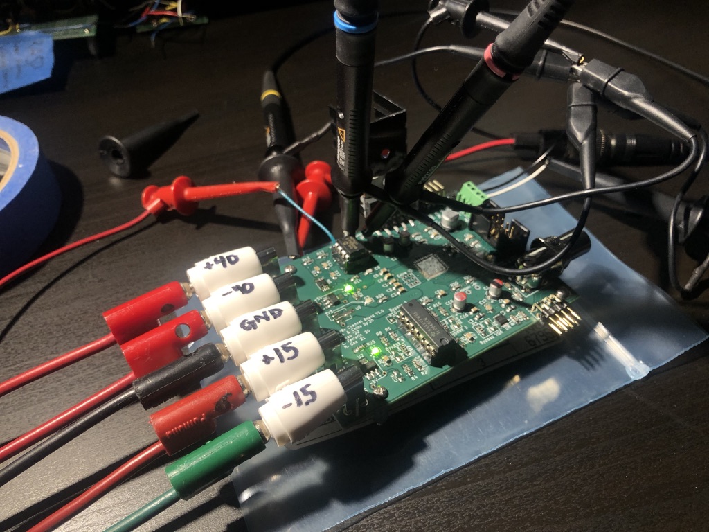
Figure 5: The new version of the boat channel driver PCB undergoing testing.
I’ve been working on finishing the bring-up process for the new PCBs. I’ve set up an electronics lab at home with equipment that I brought from the ACE lab and a few of my own tools. This summer, I plan to characterize how tightly our device can aim an ultrasound beam in my pool, and ultimately, we hope to finish a paper on the work we’ve been doing.
Comments
Post a Comment